We draw your attention to the fact that we only carry out the design, sale, installation and commissioning of systems.
Vibration monitoring and diagnostics system configuration
Bently Nevada provides solutions to protect, monitor and diagnose the condition of reciprocating compressors, offering a wide range of hardware and software specifically designed to protect reciprocating compressors.
Reciprocating compressors require high maintenance costs.
Bently Nevada protection and monitoring systems can significantly reduce maintenance costs, due to the timely detection of problems at an early stage of their development, while it is possible to achieve a reduction in maintenance costs by up to two times. The protection and monitoring system is configured in such a way as to detect problems in the operation of reciprocating compressors in a timely manner and provide measurements of the parameters that determine its performance.
Vibration monitoring and diagnostics system configuration for reciprocating compressors:

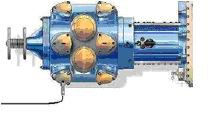
Compressor layout:
P - cylinder pressure sensors
T - temperature elements; Vel-vibration velocity sensors
Vel - vibration velocity sensors
XY - eddy current rod position sensors
Kph - phase and speed sensor


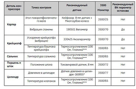
Measured parameters, applied sensors, modules, monitors
In this configuration (let's consider the example of using a two-cylinder compressor), the following sensors will be used:
-Temperature sensors
-Measuring the temperature of the gland seal of the rod - 2 sensors
- Temperature measurement of suction / discharge valves - 8 sensors
- Bearing temperature measurement - 3 sensors
- Cylinder pressure sensors: 4 pressure sensors 165855
- Stem Position Sensors: 4 x 3300XL System 8mm Eddy Current Sensors
- Crosshead acceleration sensors: 2 vibration acceleration sensors 330425
- Frame vibration speed sensors: 2 Velomitor CT 190501 sensors
-Phase sensors: 1 x 3300XL system 8mm eddy current sensor on multi-tooth wheel
Phase measurement. Keyphasor sensors
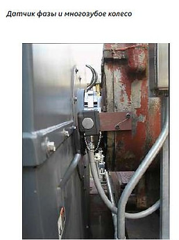
A non-contact sensor monitoring a special multi-toothed wheel on the crankshaft produces a precise timing reference every 30° in addition to one reference point per revolution. This allows measurements such as rod position and cylinder pressure to be correlated with a highly accurate crank angle measurement.
The rod position can be measured at the same point in the piston rod stroke, and the cylinder volume at each point of the stroke can be accurately calculated to generate highly accurate indicator charts (PV-curves).

Pressure measurement
The most effective way to determine the overall health of a reciprocating gas compressor is to study the cylinder pressure profile. Online access to the indicator diagram of each compressor cylinder allows you to continuously monitor the pressure in the cylinders, compression ratios, peak loads on the rods and rod reversal. This provides valuable information on the condition of suction valves, discharge valves, piston rings, seals and crosshead pin. And the System 3500's interaction with System 1™ software provides important diagnostic plots such as pressure versus volume (PV), logarithmic pressure versus volume, and pressure versus crankshaft angle.
Position sensors piston rod

Non-contact sensors for X-Y coordinates that monitor the position of the piston rod provide information about rod bending and packing wear. Continuous monitoring provides information about the maximum amount and direction of movement of the rod at the angle of the crankshaft where this maximum is observed. The source of motion can be identified, allowing preventive maintenance to be scheduled for packing replacement or crosshead repair.
Suction/discharge valve temperature
Generally, the suction and discharge valves require the most maintenance on a reciprocating compressor. Faulty valves can significantly reduce the efficiency of the compressor and also increase the load on the compound rod. When the same gas is recompressed, the leaking valve becomes hotter than the good one, which leads to an increase in the temperature of the valve chamber cover. By monitoring the absolute temperatures of the valves and the temperature difference between groups of valves, valve failures can be detected early and rectified before efficiency starts to drop.

Stuffing box temperature
Continuous monitoring of stuffing box temperature provides useful information about stuffing box problems, including excessive wear, insufficient cooling, and improper lubrication.

Bed vibration

An increase in bed vibration can indicate problems such as imbalances due to unusual pressure drop or inertial imbalances, loose foundations (such as broken grout or shims), and high torques due to excessive stem loading.
Crosshead Vibration Acceleration

A crosshead-mounted accelerometer can detect machine malfunctions caused by impact-type events such as crosshead loosening, fluid being sucked into a cylinder, or excessive clearance in a piston pin bushing.
Continuous load on the rod (hardware-calculated parameter)
The combined rod loads (inertial and gas) calculated on the crosshead provide information about the condition of the crosshead pin. Insufficient reverse or excessive stem loading can be detected and corrected before costly damage to moving parts occurs.
Sensor mounting examples:


System 3500 Chassis Configuration:

The Bentley Nevada 3500 Series Stationary Monitoring System is a fully digital, highly configurable system with a full range of features that meets the widely recognized industry standard API 670. The 3500 chassis is cabinet-mounted and fully tested prior to shipment.
The System 3500 chassis supports daisy-chaining, with the last chassis connected to the data acquisition computer. Given the possibility of future expansion of the system, additional chassis can be installed in an already delivered cabinet. The computer is used to configure the chassis, collect, store and display information about the state of the generator and monitored parameters. Alarm and warning relay contacts from the 3500 chassis are connected to the unit control system.
Information about the current values of the measured parameters and service information about the state of the system is also transmitted via a digital interface to the upper-level control system through the 3500/92 gateway. Service information, for example, refers to data on the state of the channel (working, faulty or disabled), the state of the alarm relay (worked / did not work), the values of the alarm thresholds for each channel, etc. After the initial configuration, the 3500 monitoring system can operate as a standalone monitoring and protection system, whether a computer is connected to it or not.
Alarm List - Each 3500 chassis maintains an alarm list.
The purpose of this list is to record the sequence of alarms in the event of a malfunction in the operation of the unit. System Event List - Each 3500 chassis maintains a list of system events. The purpose of such a list is to document the actions performed on the chassis. They include the following:
1. Changing alarm threshold values
2. User connection
3. Removing the module from the chassis
Access to these lists is provided through the use of the 3500 chassis configuration program.
Didn't find the right equipment?
Do not worry!
You can buy more from us than you see on the site!
Email us: [email protected]
Or call: +7 495 118 36 52
Also you can directly call our manager Oleg: +7 916 365 49 31
He will gladly help you!


